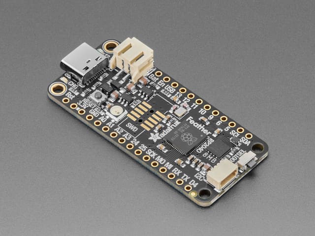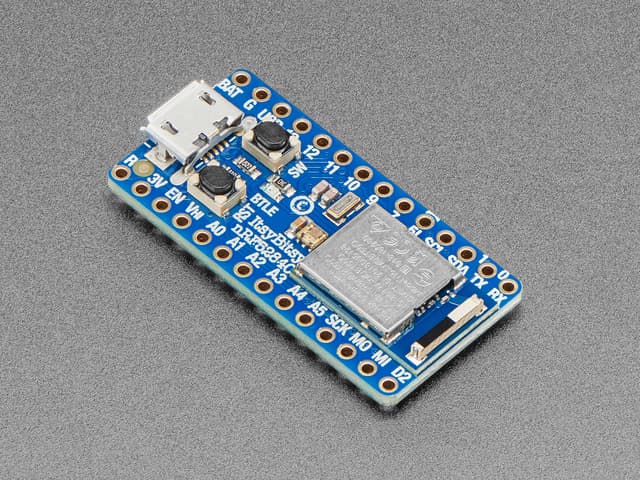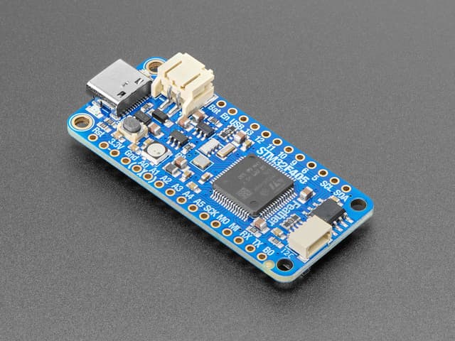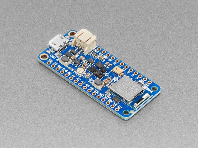
Adafruit ItsyBitsy RP2040
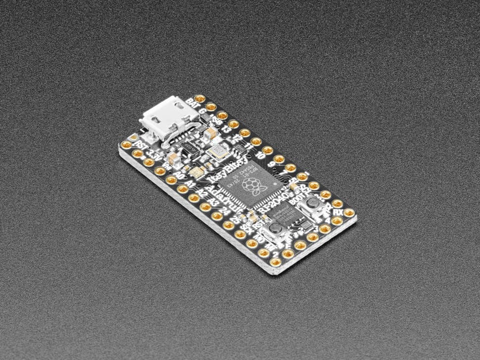
Tiny 36×18mm breadboard-friendly board with Raspberry Pi RP2040 dual-core Cortex-M0+ @ 133MHz, 264KB SRAM, 8MB Flash, 23 GPIO, 4 ADC, 2 PIO peripherals, and Micro-USB. Runs CircuitPython and MicroPython.
$9.95
Tap any value to browse matching devices
Specifications
Certifications
Components
Bus Interfaces
GPIO Map
Overview
The Adafruit ItsyBitsy RP2040 shrinks the Raspberry Pi RP2040's capabilities into a 36×18mm breadboard-friendly form factor — making it smaller than the Feather RP2040 while retaining the same dual-core performance and PIO programmable I/O. It occupies a comfortable middle ground in Adafruit's lineup: larger than a Trinket, smaller than a Feather, and perfect for projects where board size matters but pin count must not be sacrificed.
The RP2040 at the core runs two ARM Cortex-M0+ processors at 133MHz (overclockable), sharing 264KB of SRAM across six independent banks. Eight MB of SPI Flash stores programs and files. The two PIO (Programmable I/O) peripherals — each with four state machines — enable bit-bang protocols (WS2812 LEDs, I2S audio, custom serial buses) in hardware without CPU overhead. Sixteen hardware PWM channels cover servo control, LED dimming, and tone generation.
Twenty-three GPIO pins are exposed, including four 12-bit ADC inputs. All GPIO support I2C, SPI, and UART through flexible routing. A special Vhigh pin outputs the USB rail (up to 5V) for driving 5V-logic peripherals or LEDs from the regulated supply. A Digital 5 output is level-shifted to the USB voltage. An onboard RGB NeoPixel with independent 3.3V power control prevents the LED from affecting analog readings. A red LED on pin 11 serves as a traditional indicator.
The UF2 ROM bootloader enables drag-and-drop firmware updates — hold the BOOT button while connecting USB to enter mass-storage mode, then copy a .uf2 file. Both CircuitPython and MicroPython official ports are supported, as is the Raspberry Pi C/C++ SDK. Arduino support via the Mbed or earlephilhower RP2040 core is available for developers preferring the Arduino IDE.
Use Cases
3IoT
Internet of Things applications including connected sensors, actuators, and smart devices that communicate over WiFi, BLE, LoRa, or other wireless protocols.
Wearable
Body-worn computing devices including smartwatches, fitness bands, and health monitors.
Smart Home
Home automation devices for controlling lighting, climate, security, and appliances.
Resources
Where to Buy
Explore more of the directory — popular use cases, firmware, and specs to browse next.