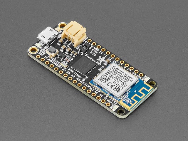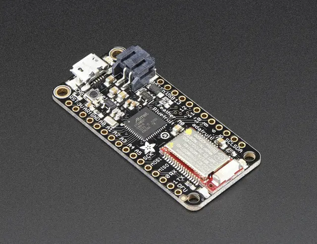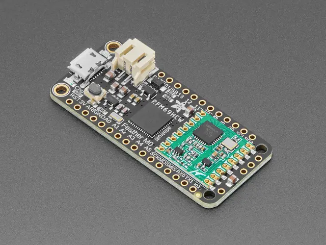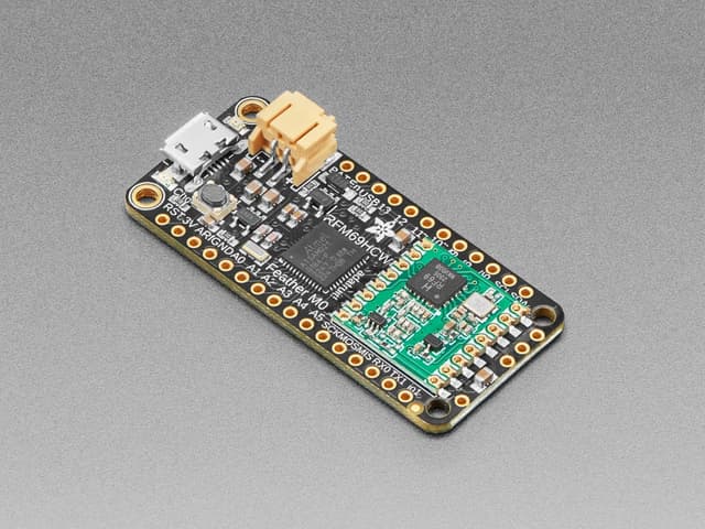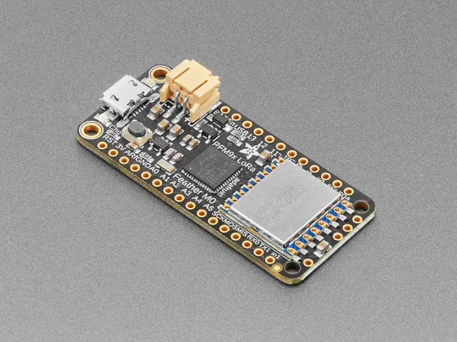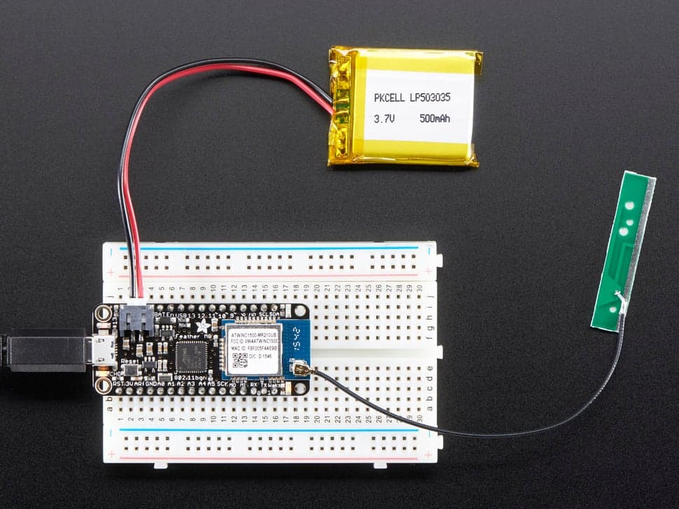
Adafruit Feather M0 WiFi with uFL
Variant of the Feather M0 WiFi (ATSAMD21 + ATWINC1500) with a u.FL antenna connector instead of a PCB trace antenna, allowing use of an external antenna for improved WiFi range.
$34.95
Tap any value to browse matching devices
Specifications
Components
FCC-certified 802.11b/g/n WiFi module with SSL/TLS 1.2 support, controlled via SPI. uFL connector for external antenna.
Bus Interfaces
GPIO Map
Overview
The Adafruit Feather M0 WiFi with uFL is identical to the standard Feather M0 WiFi (product 3010) in every technical aspect, with one key difference: instead of a PCB trace antenna, it features a u.FL connector that accepts an external 2.4GHz antenna. This makes it suitable for enclosures or installations where the built-in antenna would be blocked or insufficient range is a concern.
The board combines the ATSAMD21G18 ARM Cortex-M0+ at 48 MHz with the Atmel ATWINC1500 FCC-certified 802.11b/g/n WiFi module. It provides 256KB of flash, 32KB of SRAM, native USB (HID/CDC), 10 analog inputs (12-bit ADC), one DAC output, and 8 PWM channels. A built-in 200mA LiPo charger enables battery-powered wireless operation.
The ATWINC1500 WiFi module operates independently via SPI, handling all RF operations, WEP/WPA/WPA2 security, and even SSL/TLS 1.2. This offloads WiFi stack complexity from the SAMD21, freeing it to focus on application logic.
This variant is the go-to choice when projects are deployed inside metal enclosures, require directional antennas, or need to extend WiFi range beyond what the PCB trace antenna can achieve. An external u.FL to SMA pigtail and 2.4GHz antenna can be attached for maximum flexibility.
Use Cases
3IoT
Internet of Things applications including connected sensors, actuators, and smart devices that communicate over WiFi, BLE, LoRa, or other wireless protocols.
IoT Sensor Node
Compact wireless sensor node for collecting and transmitting environmental or industrial data.
Prototyping
Rapid hardware prototyping and proof-of-concept development with breadboard-friendly form factors and accessible development environments.
Resources
Where to Buy
Explore more of the directory — popular use cases, firmware, and specs to browse next.