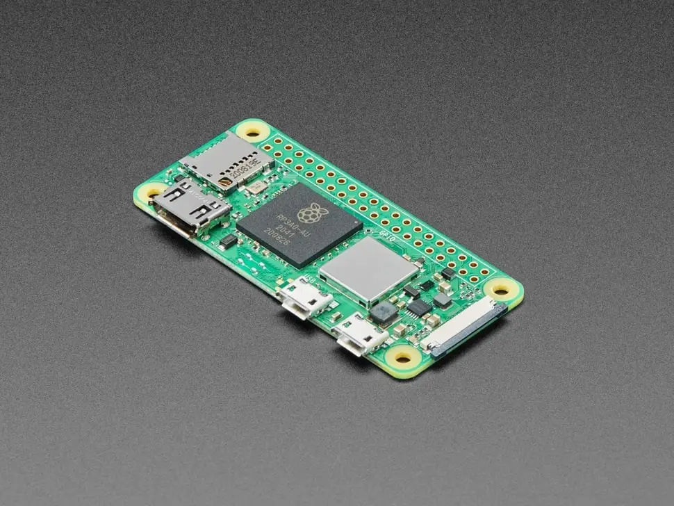
Raspberry Pi Zero 2 W
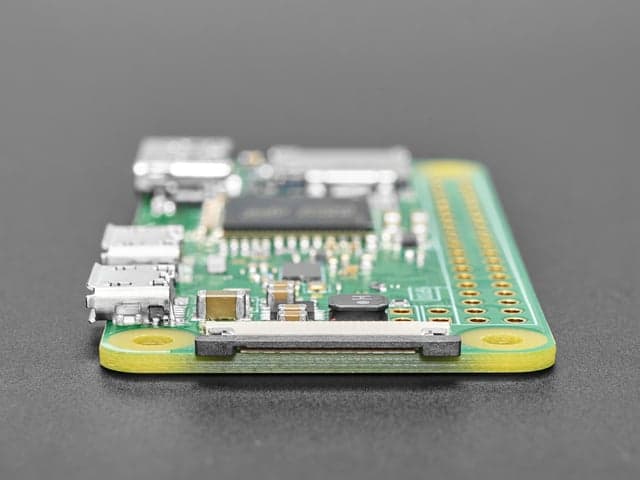
Credit-card-tiny Linux SBC with a quad-core Cortex-A53 at 1 GHz, 512 MB RAM, 2.4 GHz WiFi, Bluetooth 4.2, a 40-pin GPIO header footprint, mini HDMI, and a CSI camera connector.
$15.00
Tap any value to browse matching devices
Specifications
Components
Broadcom BCM43436 2.4 GHz 802.11 b/g/n WiFi and Bluetooth 4.2 / BLE combo radio chip.
Bus Interfaces
GPIO Map
Overview
The Raspberry Pi Zero 2 W is the second-generation Zero W, replacing the single-core BCM2835 with Raspberry Pi's custom RP3A0 package — a Broadcom BCM2710A1 quad-core 64-bit ARM Cortex-A53 running at 1 GHz, paired with 512 MB of LPDDR2 SDRAM. The result is 40% better single-threaded performance and five times the multi-threaded throughput compared to the original Zero W.
Wireless connectivity mirrors the original: 2.4 GHz 802.11 b/g/n WiFi and Bluetooth 4.2 with BLE are provided by the BCM43436 combo chip with an onboard antenna. A CSI-2 camera connector accepts the standard Raspberry Pi Camera Module (with a ribbon adapter), opening the board to computer vision projects. A mini HDMI port and composite video test pads provide video output options.
The 40-pin GPIO header footprint — unpopulated by default — is fully HAT-compatible with the wider Raspberry Pi Zero ecosystem of accessories, including the Camera Module adapter cable. Storage is provided by a microSD card, and the board runs the full Raspberry Pi OS (32-bit or 64-bit) as well as many lightweight Linux distributions optimised for the Zero form factor.
At 65 × 30 mm and 10 g, the Zero 2 W is one of the smallest capable Linux computers available, suited to wearable cameras, smart IoT gateways, and embedded-vision projects where space and weight are critical.
Use Cases
4IoT
Internet of Things applications including connected sensors, actuators, and smart devices that communicate over WiFi, BLE, LoRa, or other wireless protocols.
IoT Gateway
Acting as a local IoT gateway that aggregates data from sensors, runs MQTT broker, Node-RED, or Home Assistant, and bridges to the cloud.
Smart Home
Home automation devices for controlling lighting, climate, security, and appliances.
Environmental Monitoring
Monitoring environmental conditions like temperature, humidity, air quality, and weather data using remote sensors.
Where to Buy
Available Software
2Explore more of the directory — popular use cases, firmware, and specs to browse next.