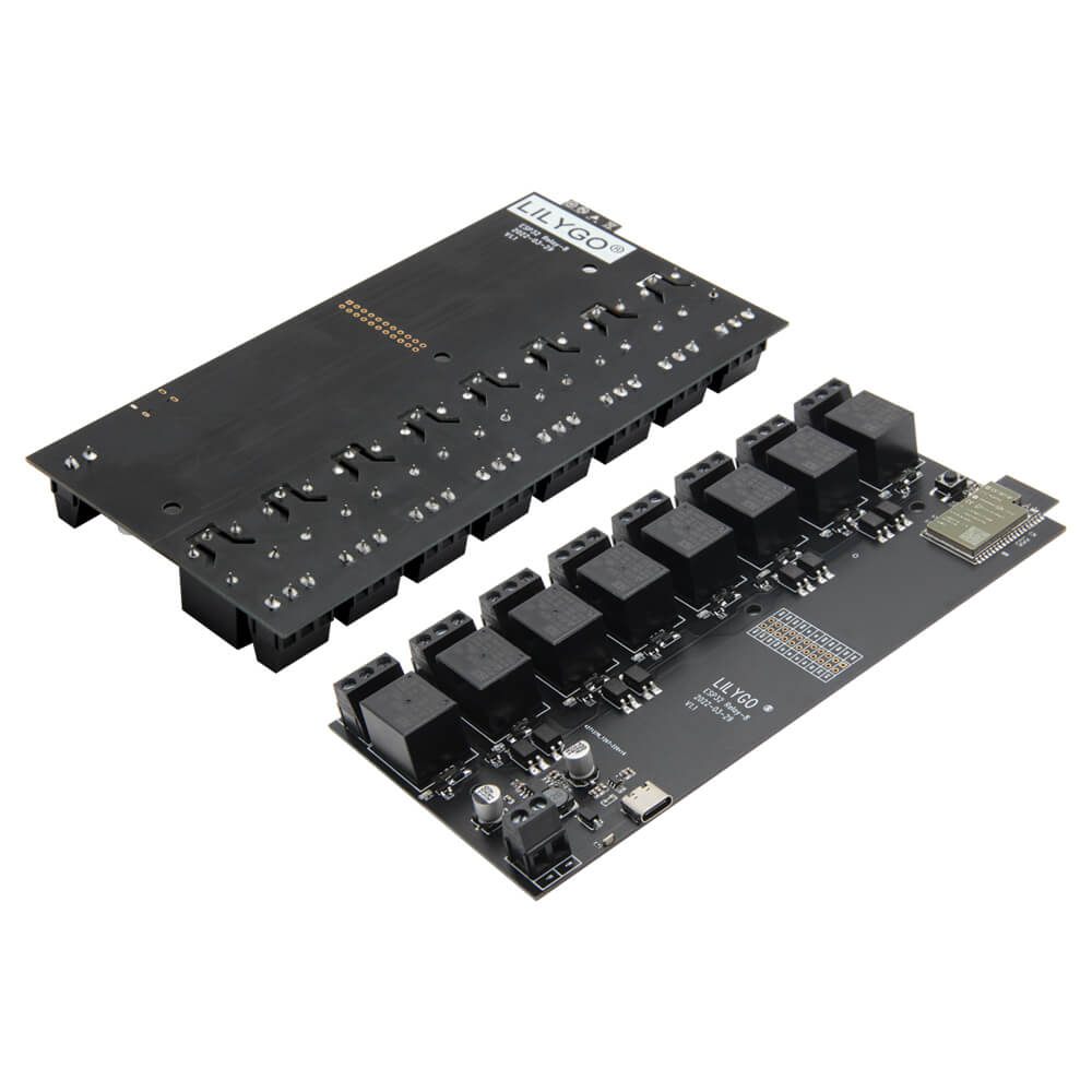
LILYGO T-Relay 5V 8-Channel Relay
ESP32-Wrover-E development board with eight optocoupler-isolated relay channels, 8 MB PSRAM, Wi-Fi, Bluetooth, and indicator LEDs for industrial automation and smart home switching applications.
$15.99
Hardware Specifications
Connectivity
Components
Dual-core Xtensa LX6 at 240 MHz with 4 MB flash, 8 MB PSRAM, Wi-Fi, Bluetooth
5V relay with optocoupler isolation, AC 250V / DC 28V max switching voltage (x8)
Resources
Where to Buy
Overview
The LILYGO T-Relay 5V 8-Channel Relay board combines an ESP32-Wrover-E microcontroller with eight independently controlled HRS4H-S-DC5V relay channels, each with optocoupler isolation for electrical safety between the control logic and switched loads. Blue LED indicators show the status of each relay channel at a glance.
Relay GPIO assignments are: K1-IO33, K2-IO32, K3-IO13, K4-IO12, K5-IO21, K6-IO19, K7-IO18, K8-IO05. Maximum switching capability is AC 250V or DC 28V. The board requires a DC 12-24V supply for the relay coils. An additional 16-pin expansion GPIO header provides connection points for sensors and peripherals.
With Wi-Fi and Bluetooth onboard, the T-Relay is well suited for Home Assistant via ESPHome or Tasmota, industrial control panels, and custom IoT automation gateways. The 8 MB PSRAM in the Wrover-E module enables complex state machines and OTA update buffers. A T-U2T USB-to-serial downloader is needed for programming as there is no onboard USB chip. An optional W5500 Ethernet shield variant (H671) is also available.
Firmware Compatibility
Tasmota firmware with template support and ESPHome YAML configurations are the most common deployments, enabling instant integration with Home Assistant and other home automation platforms. The Arduino IDE with ESP32 core works for custom firmware. LILYGO's LilyGo-T-Relay GitHub provides relay control examples and pin definitions.
Flashing Guide
- Connect the T-U2T downloader to the programming header and your computer via USB.
- Install CH9102 drivers if required.
- In Arduino IDE, select "ESP32 Wrover Module," enable PSRAM, set Flash to 4 MB.
- Alternatively, use the Tasmota web flasher or ESPHome dashboard for no-code deployment.
- Click Upload and wait for completion.
- Apply DC 12-24V to the relay power input to activate relay switching.
Related Products
ESP32This product page may contain errors. If you find any, please report them.