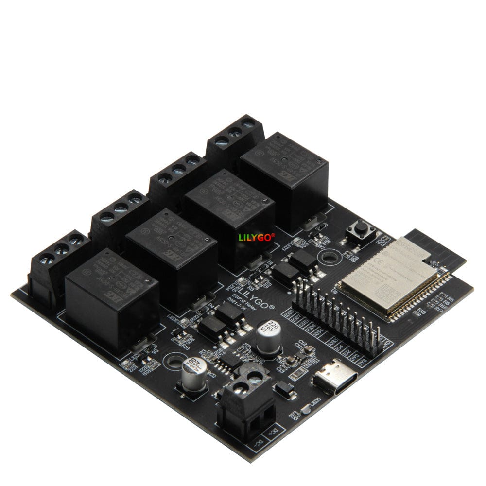
LILYGO T-Relay
An ESP32 development board with 4 optocoupler-isolated relay outputs for wireless remote switching applications, controllable via Wi-Fi or Bluetooth.
$10.01
Hardware Specifications
Connectivity
Components
Dual-core Xtensa LX6 at 240MHz with integrated Wi-Fi and Bluetooth 4.2
DC 5V relay with blue LED status indicator (4 units), optocoupler isolated
Resources
Where to Buy
Overview
The LILYGO T-Relay is a compact ESP32 development board with four integrated relay outputs, making it an all-in-one solution for wireless relay control applications. Each relay is driven by an optocoupler for electrical isolation, protecting the ESP32 from voltage spikes on the relay side. Blue LED indicators on each relay provide clear visual feedback of the current switching state.
The four relay channels are mapped to specific GPIO pins: K1 (GPIO21), K2 (GPIO19), K3 (GPIO18), and K4 (GPIO05). The board supports the standard ESP32 peripheral interfaces including UART, SPI, I2C, CAN, I2S, and SDIO through the 16 exposed GPIO pins. Programming is done via USB Type-C, and a T-U2T adapter is also supported for UART-only programming scenarios.
An optional W5500 Ethernet Shield variant is available (H671) that adds wired Ethernet connectivity alongside the existing Wi-Fi and Bluetooth, suitable for applications where a stable wired network connection is preferred over wireless.
This board is well-suited for smart home automation projects, remotely controlled power strips, irrigation controllers, industrial equipment monitoring, and any application requiring wireless switching of mains or low-voltage loads. ESPHome configuration is straightforward, making it easy to integrate with Home Assistant without writing custom firmware.
Firmware Compatibility
- ESPHome: Natively supported. Configure relay GPIOs as switch components for instant Home Assistant integration.
- Arduino: Fully supported with simple digitalWrite calls to control relay GPIOs.
- ESP-IDF: Supported for custom relay control logic.
Flashing Guide
- Install the CH9102 or CP2102 USB-to-serial driver (depending on the board revision).
- Connect via USB Type-C cable (or use the T-U2T adapter if using UART programming).
- In Arduino IDE, select "ESP32 Dev Module" and the correct COM port.
- Upload your relay control sketch. The relay GPIOs are active-LOW with optocoupler isolation — set GPIO LOW to energize, HIGH to de-energize.
- For ESPHome, define the four relays as switch components with GPIO pins 21, 19, 18, and 5.
- Refer to https://github.com/Xinyuan-LilyGO/LilyGo-T-Relay for complete pinout diagrams and example code.
Related Products
ESP32This product page may contain errors. If you find any, please report them.