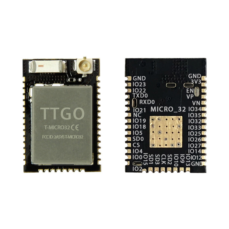
LILYGO T-Micro32 V2.0
Ultra-compact ESP32-PICO-D4 development module approximately 45% smaller than standard ESP32 boards, with an IPEX antenna connector for flexible IoT integration.
$4.24
Hardware Specifications
Connectivity
Components
SiP ESP32 with embedded 4 MB flash and crystal in a 7x7 mm LGA package
Resources
Where to Buy
Overview
The LILYGO T-Micro32 V2.0 is a miniaturized ESP32 development module using the ESP32-PICO-D4 system-in-package, which integrates the ESP32 chip, 4 MB flash, and crystal oscillator into a single 7x7 mm LGA component. The result is a board approximately 45% smaller than a standard ESP32 DevKit while retaining full ESP32 functionality.
An IPEX antenna connector allows the use of external antennas for improved RF range, making the module suitable for applications where the board is enclosed in a metal or RF-opaque housing. The compact size makes it ideal for embedding into custom PCBs for product development, wearable electronics, and space-constrained IoT sensor nodes.
Available as single units ($4.24) or 5-packs ($21.00), the T-Micro32 V2.0 is a cost-effective foundation for compact ESP32 designs.
Firmware Compatibility
The T-Micro32 V2.0 is fully compatible with the Arduino IDE using the ESP32 Arduino core. MicroPython and ESP-IDF are also supported. The PICO-D4 is transparent at the firmware level — standard ESP32 libraries and sketches work without modification. LILYGO's GitHub provides pin definitions and usage examples.
Flashing Guide
- Connect an external USB-to-serial programmer to the module's TX, RX, GND, and 3.3V pins.
- Pull GPIO0 to GND during power-on to enter bootloader mode.
- In Arduino IDE, select "ESP32 Dev Module" and the correct COM port.
- Click Upload; release GPIO0 after programming begins.
Related Products
ESP32This product page may contain errors. If you find any, please report them.