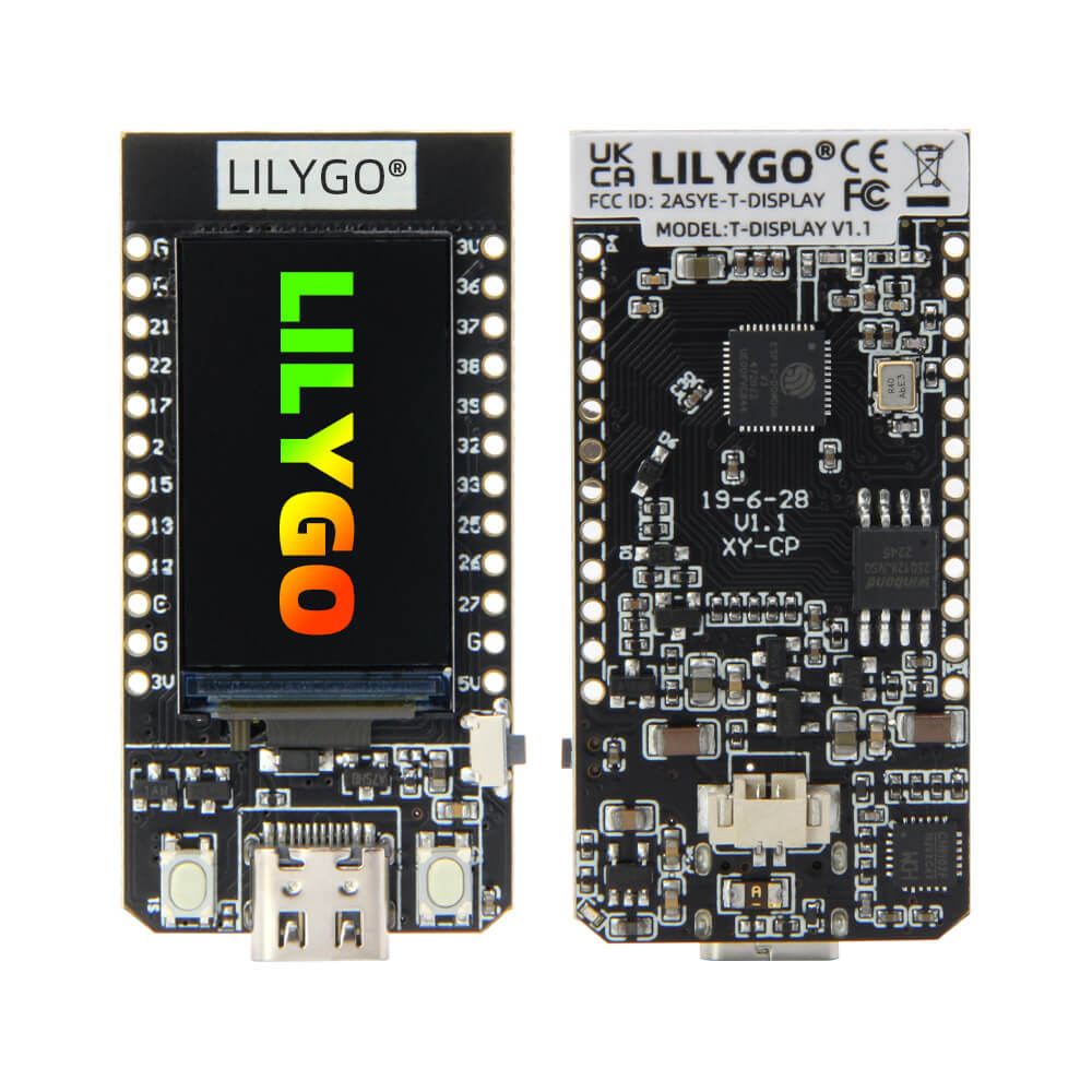
LILYGO T-Display
A compact ESP32 development board with a built-in 1.14-inch IPS LCD display, ideal for entry-level IoT projects and visual data output applications.
$8.99
Hardware Specifications
Connectivity
Certifications
Components
Dual-core Xtensa LX6 microprocessor at 240MHz with integrated Wi-Fi and Bluetooth
IPS LCD display driver for the 1.14-inch 135x240 pixel screen
USB to serial bridge chip for programming and serial communication
Resources
Where to Buy
Overview
The LILYGO T-Display is an entry-level ESP32 development board distinguished by its built-in 1.14-inch IPS LCD display driven by the ST7789V controller. The display offers a 135x240 pixel resolution at 260 PPI, making it suitable for simple UI elements, sensor readouts, and status indicators without the need for an external screen.
Built around the ESP32 dual-core Xtensa LX6 processor running at 240MHz, the board includes 802.11 b/g/n Wi-Fi and Bluetooth 4.2 with BLE. It comes with either 4MB or 16MB of QSPI Flash, making it flexible for projects that need more storage for larger firmware images or file systems.
The board exposes key GPIO pins including SPI (GPIO 18/19), I2C (GPIO 21/22), an ADC input (GPIO 34), and two onboard buttons (GPIO 0 and GPIO 35) for user interaction. The CH9102 USB-to-serial chip handles programming. Two onboard buttons provide user input, and there is a built-in battery connector with detection circuitry for portable applications.
The T-Display is well-supported with a large community and an active GitHub repository. The TFT_eSPI library is the standard choice for driving the display in Arduino projects, and MicroPython support is available for rapid prototyping.
Firmware Compatibility
- Arduino: Fully supported via the TFT_eSPI library. The official GitHub repo includes extensive examples covering display usage, Wi-Fi, and Bluetooth.
- MicroPython: Supported with st7789 drivers available for the display.
- ESP-IDF: Supported for advanced users requiring fine-grained control over the ESP32 hardware.
Flashing Guide
- Install the CH9102 USB-to-serial driver for your operating system.
- Connect the board via Micro USB cable.
- In Arduino IDE, select the board "ESP32 Dev Module" and the appropriate COM port.
- Install the TFT_eSPI library and configure the User_Setup.h file for the ST7789V display with the correct pin assignments (CS=5, DC=16, BL=4, MOSI=19, SCLK=18).
- Upload your sketch. Hold the BOOT button (GPIO 0) if the upload fails to enter bootloader mode.
Related Products
ESP32This product page may contain errors. If you find any, please report them.