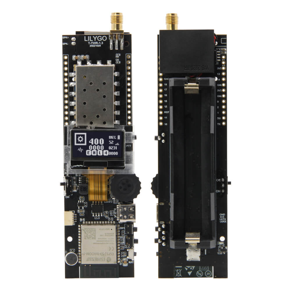
LILYGO T-TWR
ESP32-S3 handheld radio transceiver development board with 0.96-inch SSD1306 OLED, 8MB PSRAM, 16MB Flash, WiFi, Bluetooth 5, UHF/VHF/350MHz radio support, and 18650 battery.
$35.70
Hardware Specifications
Connectivity
Components
Dual-core Xtensa LX7 @ 240MHz, 16MB Flash, 8MB PSRAM, WiFi, BLE 5
0.96-inch OLED display, 128x64, I2C (SDA: IO13, SCL: IO14, EN: IO21)
Analog radio transceiver module (variant-dependent: UHF H592, VHF H602, 350MHz H603)
Resources
Where to Buy
Overview
The LILYGO T-TWR is an ESP32-S3-based handheld radio transceiver development board that combines WiFi, Bluetooth 5, and analog radio (UHF, VHF, or 350MHz depending on variant) in a single platform. The "TWR" name references its two-way radio capability, making it suitable for digital walkie-talkie projects, APRS trackers, and amateur radio applications.
At its core, the ESP32-S3-WROOM-1-N16R8 module provides 16MB of Flash and 8MB of PSRAM, with dual Xtensa LX7 cores for processing audio and radio data simultaneously. A 0.96-inch SSD1306 OLED (128x64, I2C) provides the display interface. Three buttons (Boot + IO3 + Reset) and 18650 battery support with USB fallback power are included. An upgraded T-TWR Plus model is also available on the LILYGO website.
Firmware Compatibility
The T-TWR is compatible with Arduino IDE and ESP-IDF. The GitHub repository at Xinyuan-LilyGO/T-TWR contains example firmware for radio operation, OLED display, and WiFi connectivity. The SA868 or similar radio module is controlled via UART AT commands from the ESP32-S3.
Flashing Guide
- Install ESP32-S3 Arduino core via Boards Manager.
- Connect via USB (ESP32-S3 native USB).
- Select "ESP32S3 Dev Module" with 16MB Flash and 8MB PSRAM.
- Enable USB CDC On Boot in board settings for serial output.
- Hold Boot button and press Reset to enter DFU mode, then upload your sketch.
Related Products
ESP32-S3This product page may contain errors. If you find any, please report them.