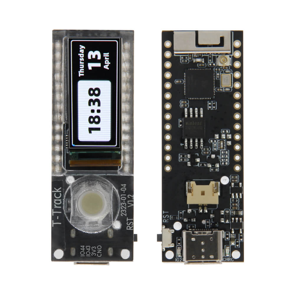
LILYGO T-Track
The T-Track is an ESP32-S3R8-based development board featuring a 1.1-inch AMOLED display and a trackball input device, designed for navigation and interactive IoT applications.
$16.98
Hardware Specifications
Connectivity
Components
Dual-core Xtensa LX7 MCU with 16MB Flash, 8MB PSRAM, WiFi and Bluetooth 5
SPI AMOLED display driver for the 1.1-inch 126x294 pixel display
Resources
Where to Buy
Overview
The LILYGO T-Track is a compact development board built around the ESP32-S3R8 processor, featuring an innovative 1.1-inch JD9613 SPI AMOLED display with a 126x294 pixel resolution and full viewing angle capability. The standout feature is an onboard trackball input device, enabling intuitive navigation through menus and interfaces without requiring an external input device.
The board supports the full ESP32-S3 ecosystem with 16MB flash and 8MB PSRAM, along with 2.4 GHz WiFi and Bluetooth 5. The 1.1-inch AMOLED display measures 10.962 x 25.578mm active area and supports 4-wire SPI communication. A 3D antenna is integrated for improved wireless performance.
Boot function is available on PIN IO00. The T-Track is well-suited for wearable devices, compact control panels, remote controls, and any application requiring a small footprint with an intuitive physical input method.
Firmware Compatibility
- Arduino IDE: Supported via Espressif Arduino core for ESP32-S3.
- PlatformIO: Streamlined build system with ESP32-S3 support.
- MicroPython: Available via the official ESP32-S3 MicroPython firmware.
- ESP-IDF: Native Espressif development framework.
Sample code and hardware documentation are available at the T-Track GitHub repository.
Flashing Guide
- Connect the T-Track to your computer via USB-C cable.
- To enter bootloader mode, hold the BOOT button (IO00), press and release RESET, then release BOOT.
- In Arduino IDE, select ESP32S3 Dev Module with 16MB flash and appropriate PSRAM settings.
- Select the correct port and click Upload.
- After flashing, press RESET to start the new firmware.
Related Products
ESP32-S3This product page may contain errors. If you find any, please report them.