LILYGO T-Relay S3
The T-Relay S3 is an ESP32-S3-based development board with 6 onboard relays, WiFi, and Bluetooth, designed for home automation and industrial switching applications.
$23.99
Hardware Specifications
Connectivity
Components
Xtensa dual-core 32-bit LX7 MCU with 16MB Flash, 8MB PSRAM, WiFi and Bluetooth 5
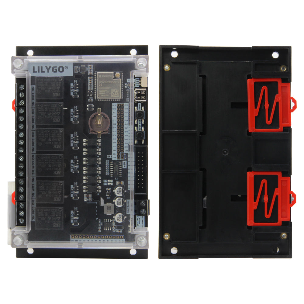
6 onboard relay channels for switching AC/DC loads
Resources
Where to Buy
Overview
The LILYGO T-Relay S3 is a powerful development board designed for home automation and industrial switching applications. Based on the ESP32-S3-WROOM-1U module with 16MB flash and 8MB PSRAM, the board features 6 onboard relay channels that can be independently controlled via GPIO, enabling switching of AC and DC loads.
The board provides 2x10PIN expansion seats with LCD connection support for attaching display modules, and supports relay chain expansion via the T-Relay Chain accessory ($15.98). WiFi 802.11 b/g/n and Bluetooth 5 connectivity allow for wireless control via MQTT, HTTP, or direct BLE commands. A T-Relay S3 W5500 variant ($6.30) is also available for Ethernet connectivity.
Built-in Reset and Boot buttons support standard ESP32 programming workflows. The board is compatible with ESPHome and Tasmota firmware for plug-and-play home automation integration with Home Assistant and other smart home platforms.
Firmware Compatibility
- Arduino: Full support via Espressif Arduino core for ESP32-S3.
- ESP-IDF: Native Espressif development framework.
- ESPHome: Can be configured with custom component definitions for relay control.
- Tasmota: Compatible with the ESP32-S3 Tasmota build, providing out-of-the-box MQTT relay control.
Source code and pin maps are available at the LilyGo-T-Relay GitHub repository.
Flashing Guide
- Connect the T-Relay S3 to your computer via USB-C cable.
- Hold the BOOT button, press RESET, release RESET, then release BOOT to enter bootloader mode.
- In Arduino IDE, select ESP32S3 Dev Module with 16MB flash and OPI PSRAM.
- Upload the firmware.
- After flashing, press RESET. Relay channels will be available via the GPIO pins defined in the pin map.
- For ESPHome: flash via the ESPHome dashboard using the appropriate YAML configuration for the T-Relay S3.
Related Products
ESP32-S3This product page may contain errors. If you find any, please report them.