LILYGO T-Display S3 AMOLED
The T-Display S3 AMOLED is an ESP32-S3-based development board equipped with a 1.91-inch high-resolution AMOLED color display, featuring SPI/QSPI interface and optional capacitive touch support.
$26.44
Hardware Specifications
Connectivity
Components
Dual-core Xtensa LX7 MCU with 16MB Flash, 8MB OPI PSRAM, WiFi and Bluetooth 5
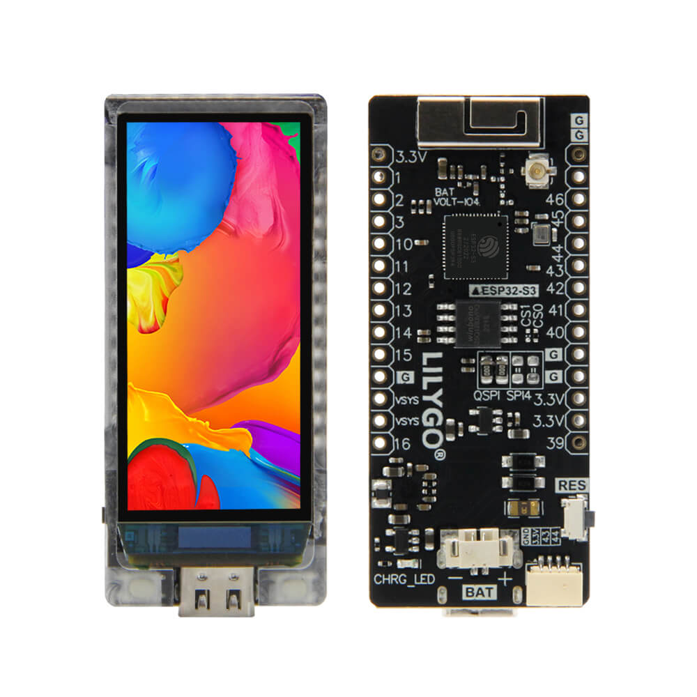
1.91-inch AMOLED with 240x536 resolution, 350 nits luminance
Resources
Where to Buy
Overview
The LILYGO T-Display S3 AMOLED is a premium ESP32-S3R8-based development board featuring a 1.91-inch AMOLED display with a 240x536 pixel resolution and 350 nits of luminance. It is part of LILYGO's AMOLED series and follows the same layout design as the T-Display family, providing a familiar pinout and footprint for existing T-Display users upgrading to AMOLED quality.
The ESP32-S3R8 processor provides dual-core Xtensa LX7 performance at 240 MHz, paired with 16MB of flash and 8MB of OPI PSRAM. The display can be driven via either a traditional 4-wire SPI interface or the faster QSPI (Quad SPI) interface, which provides up to 4x faster data throughput for smooth animations and high-refresh-rate content. WiFi and Bluetooth 5 wireless connectivity are integrated.
The board is available in touch and non-touch variants, as well as soldered and non-soldered pin configurations. A camera shield accessory is also available separately. In sleep mode, the board consumes approximately 230uA, making it efficient for low-power applications.
Firmware Compatibility
- Arduino IDE: Supported via the Espressif Arduino core for ESP32-S3. The LilyGo-AMOLED-Series library is available for the Arduino Library Manager.
- PlatformIO: Recommended for streamlined development. Available via the PlatformIO Registry.
- ESP-IDF: Supported via LilyGo-Display-IDF.
- LVGL: Compatible with both LVGL 8.x and LVGL 9.x (check examples for version-specific usage).
The LilyGo-AMOLED-Series GitHub repository contains factory examples, LVGL demos, touch examples, camera shield support, and sensor integration examples.
Flashing Guide
- Connect the board to your computer via USB-C cable. The USB port acts as both a JTAG upload port and serial monitor.
- If USB CDC is used for serial output, enable CDC_ON_BOOT in your build configuration.
- If the port is not detected, manually enter bootloader mode: hold BOOT, press RST, release RST, then release BOOT.
- In Arduino IDE, select ESP32S3 Dev Module with Flash Size 16MB, PSRAM OPI PSRAM.
- Upload your sketch and press RST to run.
- To switch between SPI and QSPI display drivers, set
LCD_USB_QSPI_DREVERto0(SPI) or1(QSPI) inpins_config.h.
Related Products
ESP32-S3This product page may contain errors. If you find any, please report them.