Build Guideadvanced
Armachat LoRa Doomsday Communicator Build
Build guide for the original Armachat pocket LoRa communicator by Bobricius, featuring a QWERTY keyboard, TFT display, RFM95 radio module, and 18650 battery for off-grid messaging up to 4km range.
Boards:STM32
Firmware:Arduino
Use Cases:Mesh NetworkingPortable DeviceLoRa & WAN
Overview
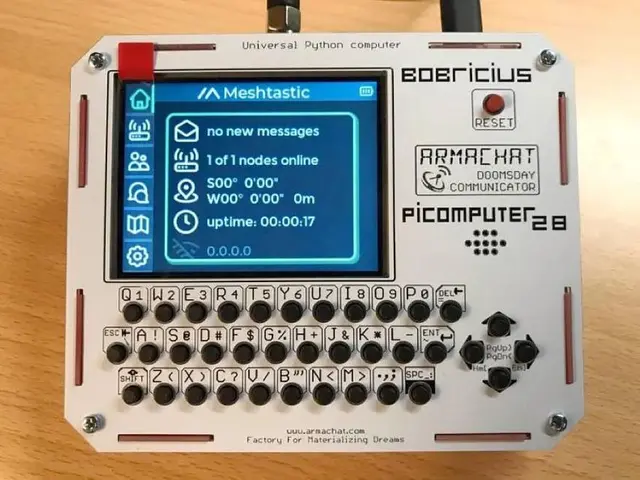
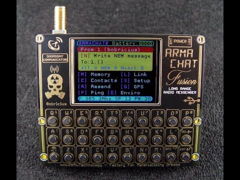
The Armachat is an open-source "Doomsday LoRa QWERTY communicator" designed by Bobricius (Peter Misenko). It provides completely off-grid text messaging using LoRa radio technology with the motto "your own network, your own rules." The device won 2nd place at the PCBWay 3rd PCB Design Contest and a Bootstrap Award at Hackaday Prize 2020.
Hardware Specifications
Pocket Version
- MCU: SAMD21E18 (Arduino Zero compatible, 256KB flash, 32KB RAM, 48MHz)
- Radio: RFM95 LoRa module (or RFM95PW high-power variant)
- Display: 1.8" TFT LCD (ST7735) or 240x240 IPS (ST7789)
- Keyboard: 30-key QWERTY (5x6 matrix)
- Power: 18650 Li-ion battery with charging circuit
- Optional: DS3231 RTC, GPS module
- PCB Size: 62mm x 77mm
- Connectivity: Native USB, I2C/UART expansion port
Desktop Version
- MCU: SAMD21G18
- Keyboard: 40-key QWERTY (4x10 layout)
- Display: 1.8" TFT LCD (128x160)
Features
- Message composition and delivery with confirmation tracking
- Contact list with auto-updated remote usernames
- Automatic message resend for undelivered messages
- Message storage in device memory
- Keyboard backlight (30-LED, on newer board revisions)
- White and black UI themes
Range Testing Results
Using LoRa Spread Factor 12 at 865.2MHz:
- 700m from garden desk (no line of sight)
- 1.5km from window (4m elevation)
- 4.3km+ from attic window (10m elevation)
Build Instructions
- Hand-solder the SAMD21E18 and passive components to the PCB
- Burn the bootloader using an Atmel-ICE programmer (or cheap alternative included in repo)
- Upload firmware via USB mass storage (UF2 format)
- Laser-cut the front panel using provided DXF files
- Assemble the case with 18650 battery holder
Resources
- Schematic available as PNG in the repository
- Front panel files in DXF and Gerber format
- Pre-built UF2 firmware files for black and yellow board variants
- Arduino IDE compatible development environment
Awards and Recognition
- PCBWay 3rd PCB Design Contest: 2nd Place, "Best Design"
- Hackaday Prize 2020: Bootstrap Award (Community Vote)
- Featured on Hackaday: "A LoRa IM-Me For The End Of The World" and "An Off-The-Grid Instant Messaging Platform"