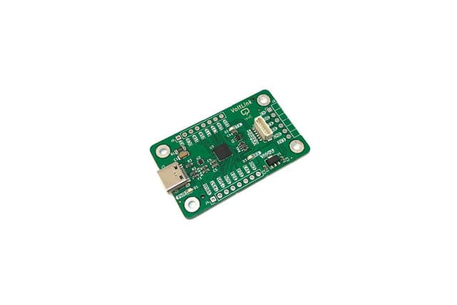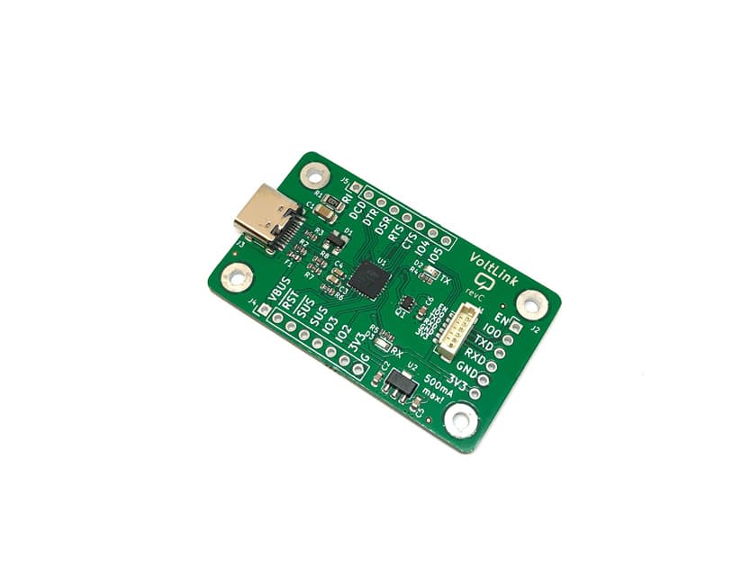
VoltLink Hardware Evolution — From Rev A to Rev E Design Walkthrough
Video series documenting the iterative hardware design of the VoltLink CP2102N across five PCB revisions, covering chip selection, ESD protection, DFM optimization, and a CP2104 LED bug discovery.
Voltlog documented the complete hardware evolution of the VoltLink USB serial adapter across a series of blog posts and videos, providing an educational walkthrough of iterative PCB design, component selection, and design-for-manufacturing (DFM) optimization.
Revision A — Original Design (Voltlog #356)
The first VoltLink was built around the CP2104 chip, motivated by frustration with unreliable counterfeit chips found in cheap AliExpress USB serial adapters. Key design goals:
- Use a genuine Silabs serial converter chip from a trusted distributor
- Break out all chip I/O to standard headers for maximum flexibility
- Include auto-reset circuitry for ESP32 bootloader entry
- Full KiCad open-source design
CP2104 LED Bug Discovery (Voltlog #359)
During Rev A testing, Voltlog discovered that the CP2104's RX/TX status LEDs were not responding during serial communication, despite the serial port functioning correctly. This led to the investigation and eventual chip change.
Revision B — CP2102N Upgrade (Voltlog #396)
- Switched from CP2104 to CP2102N in QFN28 package due to chip shortage and the LED bug
- Upgraded ESD protection to TPSP0503 with lower capacitance for better USB signal integrity
- Maintained the same board dimensions and connector layout for backward compatibility
Revision C — Manufacturing Optimization (Voltlog #405)
- No new functionality — focused entirely on making the design easier to manufacture and assemble
- Retained all Rev B features: USB-C, 3M baud, 500mA overcurrent protection, ESD protection
Revision D — Polish and Cost Optimization (Voltlog #414)
- Added power status LED near USB connector for quick power verification
- Replaced 4 individual 1k resistors with a single resistor network to reduce BOM cost and pick-and-place operations
- Increased decoupling capacitor from 4.7uF to 10uF to match the regulator output cap, reducing unique part count
- Added KiBuzzard aesthetic labels to the PCB silkscreen
Revision E — Current Release
The latest revision with further schematic refinements, reflected in the VoltLink_schematic_revE.pdf file in the GitHub repository.
Lessons for Hardware Designers
This project series demonstrates several important hardware design principles:
- Iterative improvement — each revision addresses specific issues without over-engineering
- DFM awareness — consolidating components reduces assembly cost and error rates
- Genuine components matter — counterfeit chips cause real reliability problems
- Documentation — sharing the design journey helps the community learn